Magnetic Field Controlled Robot
Group members: Charles Surianto (Head chef), Musa Charara, Peter Woolsey, Nathan Roorda, Lingxiao TianCourse: ELEC 291: Electrical Engineering Design StudioTable of Contents
- Use of process
- Need and Constraint Identification
- Problem Specification
- Solution Generation
- Solution Evaluation
- Safety & Professionalism
- Detailed Design
Introduction
Low-frequency EMF (Electromagnetic Fields) are useful for small ranged wireless communication because they are inexpensive, have finer control on short distances, and have lower power consumption compared to radio or infrared communication [1]. Considering these merits, we used LFM (Linear Frequency Modulated) waves to build a short-ranged, wirelessly controlled robot car — similar to an RC (remote-controlled) toy car.
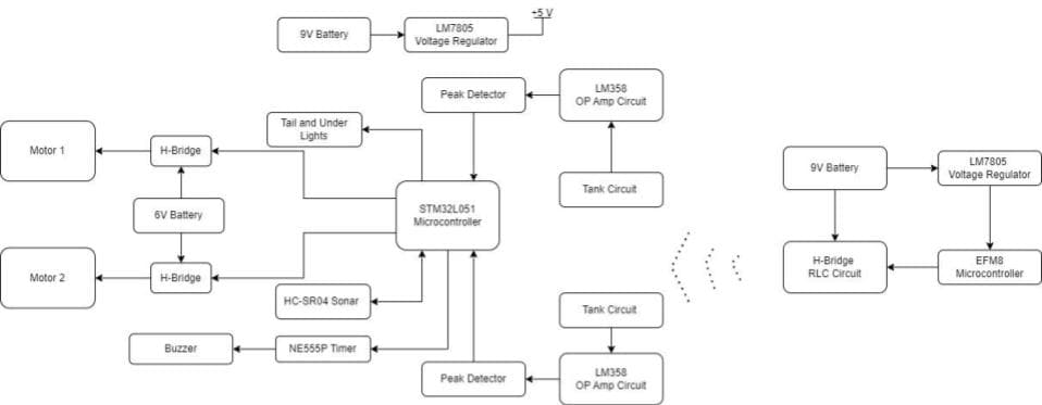
The project consists of two battery-powered devices: a remote and a robot. The remote is constructed using the EFM8 microcontroller to send movement commands to an electric motor-powered robot. The robot is based on the STM32L051 microcontroller and has two modes of operation: beacon/tracking mode and controller mode. In the tracking mode, the robot would maintain its angle and distance away from the remote. When toggled into the controller mode, the robot follows the directional commands sent by the joystick in the remote; directions such as North (relative to the robot), East, Southwest, etc. In this project, we designed the hardware and software of the robot car to best suit the needs of our stakeholder and specifications. Our final product reflects this goal, as the robot is capable of fine motor control over a moderate distance of 40 cm and is outfitted with useful features such as multi-colored RGB headlights, and a sonar powered obstacle detection and alarm system.
Investigation
Idea Generation
Our team met to create a brainstorm to create a rough design for the robot and its controller. We decided the best approach would be to split the robot and controller workload and reach a minimum viable product for each. We regularly held whiteboard discussions to formulate how we could best design elements such as the information transmission system, board circuitry, general coding strategy, and the hardware interface for the user (See Appendix D). Moreover, we employed the use of GitHub to collectivize our codebase into one place. This adds a level of source control that enables us to branch off the main backup to try new ideas without losing our code that already works.
Investigating Design
To ensure easy debugging, we tested both the controller and robot individually. We first tested the output of the controller across the inductor. The testing found that we were able to achieve approximately 300 VPP across the inductor. We were also able to toggle on and off the carrier signal with a second timer.
For testing the robot, we first tested that the robot was able to move around with a pre-programmed route to make sure that the mechanical design of the robot was correct. After ensuring that the mechanical design was valid, we tested the receiving capabilities of the robot. We wrote a program that was able to identify the amplitude of the signal received by the robot. In addition, using the LM393 comparator, we are able to create a digital output that goes high when the output signal of the LM358 is greater than the threshold voltage created by the voltage divider. After ensuring that both the controller and robot are able to function independently, we were able to confidently get to work on the communication protocol between the two devices.
Data Collection
During this project we collected data to help us properly implement certain features of the robot, mainly the frequency transmission from the controller, the receiver on the robot and the sonar sensor attached to the front of the robot. To ensure our controller was working and to test the range of the robot we attached an LED and capacitor to one of the spare inductors to help us see how strong the transmission was (see appendix E). Using this setup we were able to measure our range early on in the project before our receiver was fully implemented. As for the receiver, we were able to test the received signal using an oscilloscope measuring voltage across the inductor.. Additionally, we tested our sonar sensor using an oscilloscope and function generator setup as well. We attached one probe to the trigger pin and one probe to the echo pin of the sonar sensor. To confirm it was working as per the data sheet, we fed the trigger pin a square wave with a period of 10µs and tested whether the echo pin outputted correctly or not. We continued to probe the echo pin throughout the implementation of the sonar sensor to help us identify bugs easily and ensure the data collected matched the expected results (see appendix F).
Data Synthesis
Transmitter

The timer clock is ticking at 72 MHz. The minimum frequency achievable with the auto-reloading 16 bit timer is 34.333 Hz with a prescaler of 5 and reload value of zero. With respect to data transmission, we used pulse-width modulation to define different commands. We made a prototype in the breadboard and tested the output in the oscilloscope. After testing it to make sure it can toggle between beacon mode and controller mode, we installed a joystick to implement.
Receiver
For the amplifier part, we chose a 56k resistor and a 1k resistor, which generate a gain of 56 in the non-inverted amplifier (LM358P) and we made sure the voltage gain is appropriate to feed to the peak detector. Since two tank circuits showed different voltages when they are in the same distance from the transmitter, we added an extra amplifier to correct the voltage.
Sonar
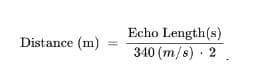
We used the HC-SR04 sensor which has a range from 2 cm to 400 cm and 15 degrees measuring angle. We first tested sonar alone and observed the waveform changes in the oscilloscope to see its response to the objects. Which we programmed using the formula:
Our group synthesized data by firstly figuring out design requirements, then building prototypes and debugging in electronic devices. We decomposed the project and assembled components piece by piece. Finally, we focused on extra features and explored methods for higher standards.
Anaylsis of Results
Our team appraised the validity of conclusions by extensively testing the functionality of each part of the robot and remote. When encoding our signal commands with a varying duty cycle, we encountered limitations regarding the accuracy of our EMF signal readings. The length of the duty cycle reading would become distorted depending on the robot’s distance from the controller, which caused the robot to execute the wrong actions when far away from the controller. For example, if a command with a 70% duty cycle was sent from the controller, a 50-60% duty cycle would be received by the robot when far away from the controller. To attain the most accurate signals, we changed our signal encoding strategy to use frequency modulation, which allowed our robot to move according to correct and consistent command signals from a distance. For future improvements to our tracking robot, we plan to extend the range of our data signals by adding capacitors to our power rails and optimizing our circuit with shorter wiring.
Design
Use of Process
To create our overall design approach, we first discussed all the main tasks of the project and split them into three main categories: the transmitter and controller, the receiver and car, and the sonar functionality and extra features. Our group split into three focus groups, each designing one of the aforementioned categories. Each subteam would share their ideas and progress to the rest of the team, where we collectively explored the ideas further using whiteboard drawings and voted on which ideas to implement. This approach allowed everyone to focus on specific aspects of the project, while allowing everyone to contribute and have an understanding of the project as a whole.
Need and Constraint Identification
Our stakeholders include anyone who needs a small robotic car that utilizes low frequency electromagnetic fields to communicate. For the needs of our stakeholders to be met [3], our robotic car must have:
- Accurate and reliable movement.
- Controls that are intuitive and easy to use.
- A reasonably long range of communication.
- Safety features that prevent damages to the car.
Possible applications of this technology include robots that can operate effectively in hazardous environments, small spaces, or even underwater. The effectiveness of this technology is predominantly constrained by the maximum range that reliable signals can be received. This is due to the fact that nearly all projects in which this technology is utilized benefits greatly from a great signal range.
Problem Specification
Based on the stakeholder needs listed above, our team decided that our remote controlled car must fulfill the following requirements:
- The robot and the remote are battery powered.
- The system has two modes: tracking mode and controlled mode. In tracking mode, the car maintains a fixed distance from the controller, while controlled mode allows the car to be controlled by a joystick.
- Negligible delay when responding to commands sent by the controller.
- The robot communicates with the controller using signals encoded in electromagnetic fields and transmitted using an inductor.
- Minimum range of 50 cm.
- The robot must stop and beep when there is an obstacle within 3 cm.
These design specifications allow our robot to have accurate and reliable movement, intuitive controls, safety features, and a reasonable range of communication.
Solution Generation
Joystick
As outlined above in the problem specification section, one of such ideas we pursued was the implementation of a joystick controller. It was evident to us that using buttons made controlling the robot more cumbersome and harder to use. Our initial joystick idea was to implement a simple movement system consisting of North, East, South and West directions. However, we later branched out to include Northeast, Southwest, etc. (See Appendix D for joystick movement sketch). Our ideal remote controller is that we can use one button to toggle between beacon mode and controller mode.
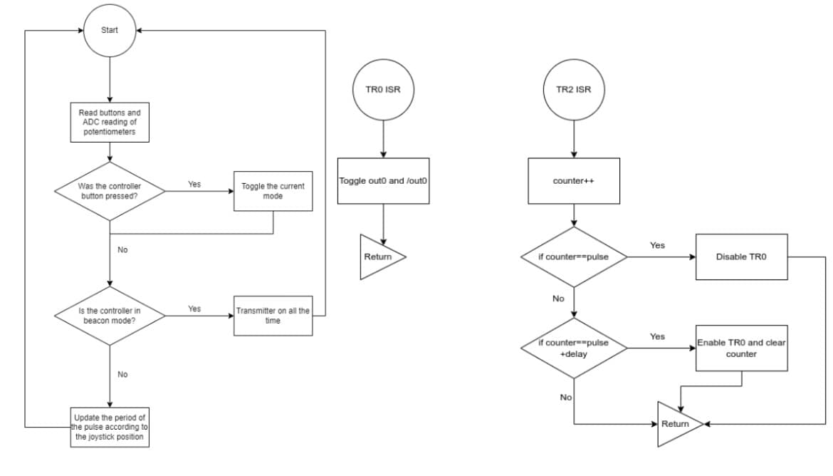
For the firmware finite state machine, we implemented the state diagram shown on figure 2 where each state will have its own run-once part and loop part which will be further explained in the Finite State Machine of Detailed Design section.
Encoding Information
We came up with the idea of PWM similar to RF controllers which varies the duty cycle of the signal which can be detected by the receiver. Later however we found out that this protocol had a major flaw which urged us to use another protocol. Since the rise and fall time changes depending on the peak voltage, as the distance from the remote changes, the signal is distorted making it useless. We quickly changed the protocol to modulating the frequency instead, this way while the rise/fall time still changes but is identical which shifts the whole signal and automatically compensates for the distortion.
Obstacle Detection
For obstacle/wall detection, we came up with the idea of using sonar sound waves. Its range of detection (2 cm to 4 meters) [4] was perfect for our use case of detecting objects within a short range. After testing the responses of the sonar to obstacles, we combined it with the buzzer in the receiver.
Solution Evaluation
After a set of features neared completion, our team would meet and discuss whether anything else needed to be added or tweaked. To figure out what needed to be tweaked, we performed a few field tests on the feature being evaluated. We would then compare the results of this field test with the project requirement specifications. For example, after we implemented the transmitter on the controller along with the joystick, we tested controlling the robot in both beacon and controller mode. We then realized that the joystick inputs were very inconsistent using PWM modulation for transmitting. For this reason, our team decided to implement transmission using frequency modulation instead to ensure that our joystick outputs were read correctly and met full requirements. As for bonus features like the sonar sensor, we would discuss the results of the field test and decide whether or not the bonus feature was adding enough extra functionality or not to the robot.
Safety & Professionalism
As with any engineering project, we always kept safety as our highest priority. Following the general guidelines of the engineering code of ethics (from Engineers and Geoscientists BC) [2], we ensured our environment was as safe as possible by making sure each group was aware of the hazards before working on it. For instance, group members building the H-bridge and inductor circuit conducted a small group meeting to review the potential dangers of working with (relatively) high voltage circuits. We created safety protocols to alert people nearby not to touch the inductors when its in operation, and turned off the circuit to prevent it from overheating when we were not using it. We kept a similar level of precaution for other parts of the project, and held each other to high safety standards.
Lastly, we are privileged to have access to Macleod’s labs, and so we always ensured to uphold lab rules and kept our workspace clean and devoid of food or drinks. We actively encouraged the contribution of all members and tried to incorporate everyone’s input into our final design and implementation.
Detailed Design
Robot
There are two H-bridges which drive two motors separately, these H-bridges are controlled using two pins each connected from the microcontroller. To drive a motor, the inputs of the corresponding H-bridge must have alternate voltages and depending on which side is high, the motor spins forward or backward. The H-bridges are powered using a separate battery (6V) which decouples the noise from the motor from the rest of the robot’s system.
The receivers were designed with simplicity in mind which reduced the number of components that were needed. The gain of the Op-Amp was chosen such that the noise was minimal and there is enough range. The voltage on the inverting input of the comparator was chosen such that the output is still high when the transmitter is barely outside of the range (this enabled the robot to know when to change mode).
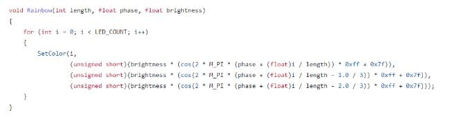
There are three WS2812B addressable RGB LEDs connected in series, two of which function as tail lights and the last one is for underglow. In the tracking mode, the tail lights and the underglow both cycle color whereas in controlled mode, the tail lights function like a car’s tail lights (brake light, reverse light, etc.) and the underglow remains the same.
There is a sonar sensor which enables the robot to know if there is an obstacle or not in front of it. The robot uses a timer in both PWM mode and input capture mode to trigger the sonar and read the distance respectively. This way the reading is non-blocking which increases the overall performance of the robot. There is a buzzer circuit which is controlled using a pin from the microcontroller. This buzzer is activated whenever there is an obstacle within 3cm of the robot.
Remote
The center of the remote is the H-bridge which drives the LC circuit at its resonance frequency to achieve high voltages. The H-bridge is driven by the EFM8 which has two pins, out0 and out0. Both pins are toggled at a frequency of approximately 32kHz, creating a sine wave with a frequency of 16kHz across the inductor. This resonates with the LC circuit creating a large peak to peak voltage and a high current flow, which is what we need to create the magnetic radiation for coupled inductance.
In order to turn the carrier signal of 16 kHz into a data transmission, we used a second timer, TR2, to enable and disable timer zero. During beacon mode, timer 0 never turns off, creating a constant signal on the robot. When using manual control, the controller creates constant length pulses of the carrier signal being enabled, followed by variable length periods of the signal being off. By controlling the length of the gaps between the pulses, we are able to encoding commands, which can be decoded on the robot.
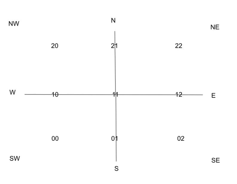
The main loop of the code on the controller is responsible for reading the users input. First checking if the joystick has been pressed, and switching states if it has. If the current state is beacon mode, the delay between pulses is set to zero, otherwise the pulse delay is set based on the ADC readings of the two pins connected to the potentiometer.
Solution Assessment
To ensure that our robot passed all the requirements and fulfilled the needs of our stakeholders, we evaluated the accuracy and performance of the full robotic system. In order to test the range and accuracy of our signals, we measured the transmitted and received signal, as well as the distance of the robot from the controller. In our first test, we encoded our signal by varying the duty cycle of the signal and measured each signal at intermittent distances of separation.
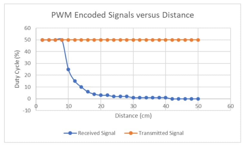
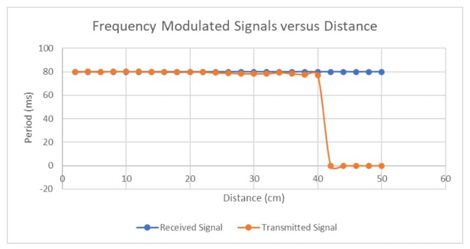
From our results, we determined that the signal our robot received was not consistent with the signal sent by the controller. We noticed that since the rise and fall time of the signal changes depending on the peak voltage, as the distance from the remote changes, the signal gets distorted. From this observation, our team decided to encode our signals using frequency modulation.
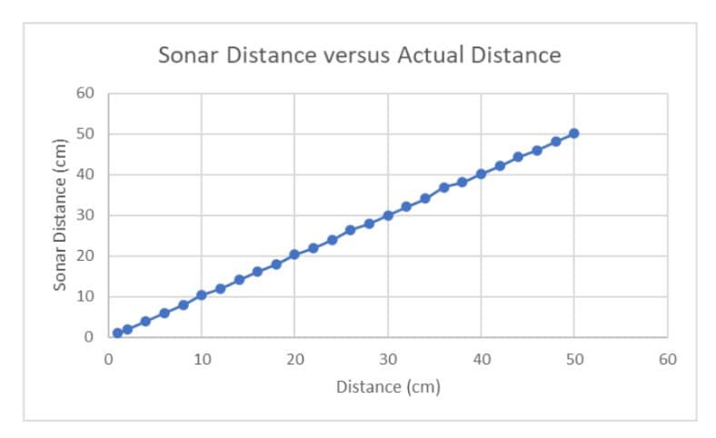
From our new data, we observed that the frequency modulation encoding had the same rise and fall time changes, but shifts the whole signal and automatically compensates for the distortion. We also tested the accuracy of our sonar sensors, measuring the actual distance between our sensor and a wall at varying distances.
We found that our sonar distance measurements and calculations were consistent with the actual distance from the wall. Based on our system analysis, our project excelled in consistently reading signal commands and sonar signals accurately, but lacked a long signal transmission range. In the future, we will build on these strengths and weaknesses to develop a more complete system.
Life-Long Learning
Some members of our group brought additional knowledge and skills from personal projects, but most of the knowledge our team used came from classes we took this year. From ELEC 201, we applied our study of Op-Amps and Transistor circuit design, in both the transmitter and receiver. We also used knowledge about frequency responses of RLC circuits that we learned in ELEC 202. Lastly, we learned about the inductive coupling, the method of wireless power transfer we used, in both ELEC 202 and ELEC 211. When learning about coupled inductance, the primary example was always transformers, which meant that we had to research on our own about antennas. There are two courses that would teach us more about antennas and their design, ELEC 404 and ELEC 401. In addition, we could learn more about the principles of robotics in ELEC 442.
Conclusions
The design of our remote controlled car supports an intuitive user interface, additional safety features to prevent collisions, and multiple control methods. The most notable problem we encountered was accurate and consistent encoding of commands over a variety of ranges. To address this we tested multiple encoding protocols, before finally deciding on using the delay between pulses. For future projects, we will do more research in order to improve signal range and noise reduction. Our team spent approximately 110 man hours working on our remote control car project.
References
[1] Ruan Lourens, “Low-Frequency Magnetic Transmitter Design”, Microchip Technology Inc., 2008.
[2] Engineers and Geoscientists BC, “Code of ethics”, Engineers and Geoscientists BC, 2023
[3] J. Calvino-Fraga, “Project 2, Magnetic Field controlled robot”, University of British Columbia
[4] SparkFun Electronics, “Ultrasonic Ranging Module HC - SR04”, SparkFun Electronics, 2016
Bibliography
How to Mechatronics, “Ultrasonic Sensor HC-SR04 Tutorial”, Youtube, July, 2015